Raspberry Pi — открытие по интернету
Заполните несколько параметров — и сервер соберёт готовый Python-скрипт под вашу плату. Останется скопировать его на Raspberry Pi и запустить сервисом: прошивать ничего не нужно.
1. Платформа
Выберите платформу — от неё зависят следующие поля.
2. Готовые пресеты
Нажмите на пресет — параметры подставятся в форму ниже. Дальше можно поправить вручную.
Готовые WiFi-реле (заменить программу)
Собрать самому на ESP32
Платы-контроллеры на ESP8266
Готовые WiFi-реле на ESP8266 (Sonoff и подобные) для открывания привода не подходят — они коммутируют 220 В, "сухих" контактов у них нет. Нужна обычная плата + отдельный релейный модуль (см. "Что ещё понадобится" ниже) — он и даёт свободную пару контактов "как кнопка".
Raspberry Pi
К обычной плате Pi реле цепляется на GPIO — тот же релейный модуль, что и для ESP (см. "Что ещё понадобится" ниже). Либо возьмите релейный HAT, который надевается прямо на разъём Pi.
Что ещё понадобится
Эти картинки не нажимаются — просто показываем, как выглядят компоненты.
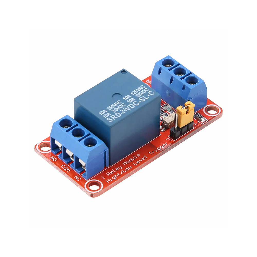 Релейный модуль
Один и тот же для ESP32, ESP8266 или Raspberry Pi — любой платы без реле на борту. Три провода к контроллеру: управление, питание и общий минус "земля" (GND). Выход реле — на привод
Релейный модуль
Один и тот же для ESP32, ESP8266 или Raspberry Pi — любой платы без реле на борту. Три провода к контроллеру: управление, питание и общий минус "земля" (GND). Выход реле — на привод
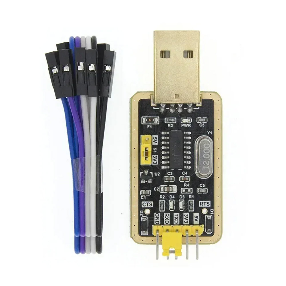 USB-UART переходник
Нужен тем, у кого нет своего USB: готовые Shelly и модули без обвязки ESP32/ESP8266. Платам с USB (DevKit, Wemos) не нужен
USB-UART переходник
Нужен тем, у кого нет своего USB: готовые Shelly и модули без обвязки ESP32/ESP8266. Платам с USB (DevKit, Wemos) не нужен
3. WiFi
Имя сети и пароль записываются прямо в программу устройства. Если потом смените WiFi — нужно будет собрать и загрузить программу заново с новыми данными.
3. Сеть
Raspberry Pi подключается к сети средствами ОС — настройка WiFi или Ethernet идёт через стандартный raspi-config, NetworkManager или /etc/wpa_supplicant/wpa_supplicant.conf. Скрипту WiFi-креды не нужны.
Если ставите впервые — для Pi Zero W удобнее всего прописать SSID и пароль на boot-разделе SD-карты в файле wpa_supplicant.conf. Для Pi 4 / 5 проще через raspi-config nonint do_wifi_country RU и raspi-config nonint do_wifi_ssid_passphrase MyHomeWiFi секрет.
4. Учётные данные устройства
Добавьте в приложении объект типа "Устройство" — после регистрации приложение покажет код устройства. Вставьте его в поле ниже: по нему прошивка подключается к серверу.
5. Замок и реле
6. Кнопка выхода и автозакрытие
Кнопка и концевик используют встроенную подтяжку пина, резистор не нужен. У ESP32 на пинах 34–39 подтяжки нет, для них они не подходят: возьмите другой пин.
Кнопка и концевик используют встроенную подтяжку пина, резистор не нужен. У ESP8266 не берите GPIO16 (нет подтяжки) и GPIO0, 2 и 15: от них зависит, как плата запускается. GPIO4, 5, 12, 13 и 14 безопасны.
7. Светодиоды (опционально)
До трёх индикаторов: связь с сервером, "открыто" и для бистабильного замка "закрыто". Оставьте -1, если они не нужны.
Хотите посмотреть исходник, поправить его вручную, скачать .ino или поделиться ссылкой — нажмите "Открыть в редакторе". Это ровно тот код, который сервер собрал в .bin.
Привязать к приложению
В приложении откройте объект "Устройство" → "Привязать к приложению", скопируйте код (он начинается с ENTX-BIND:), вставьте ниже и нажмите "Записать в контроллер". После этого контроллер открывается только по команде вашего приложения — секрет идёт в контроллер по USB, минуя сеть и сервер.
Контроллер должен быть уже прошит и подключён по USB. Если приложение перевыпустило ключ — повторите привязку с новым кодом.
Проще: вставьте код сюда до нажатия «Загрузить в контроллер» — ключ запишется сразу после прошивки, в той же USB-сессии.
Установка на Raspberry Pi
После того как скачали сконфигурированный entrixy.py:
- Положите файл в
/opt/entrixy/entrixy.pyна Pi (можно черезscp). - Установите зависимости:
sudo apt install python3-websockets python3-rpi.gpio(для Pi 5 используйтеpython3-rpi-lgpio). - Скачайте systemd-сервис: entrixy.service, положите в
/etc/systemd/system/. - Включите автозапуск:
sudo systemctl enable --now entrixy. - Проверьте:
sudo journalctl -u entrixy -f→ должно появитьсяauth OK.
Скрипт сам реконнектится при потере соединения и поднимается после ребута Pi.
Подключение реле к приводу
На выходе устройства задействуете два контакта: NO (нормально разомкнут) и COM (общий). Эти два провода идут на клеммы "Кнопка открытия" в плате управления вашего привода.
| Привод | Куда подключать NO/COM |
|---|---|
| BFT (Phobos, Deimos, Ares) | Клеммы START или OPEN (обычно номера 21–22 в схеме) |
| CAME (BX, ATI, BK) | Клеммы 2–7 (open) или PED для калитки |
| NICE (Robus, Run, Spin) | Клеммы 1–3 (пошагово) |
| FAAC (740, 844, 391) | Клеммы OPEN A (открыть полностью) |
| DoorHan (Sliding, Arm) | Клеммы CMD + GND |
| Шлагбаум барьерного типа | Кнопочный пост "Открыть" — параллельно его контактам |
| Домофон (Cyfral, Vizit, Eltis) | Реле параллельно кнопке открытия двери (трубка) или прямо на клеммы магнитного замка |
Точные обозначения смотрите в инструкции к плате управления. Если плата уже подключена и работает, ищите два провода, которые идут от кнопочного поста "Открыть" — параллельно им и подключаете NO/COM.
Как добраться до UART на готовых WiFi-реле
Готовый корпус Shelly Plus 1 не имеет внешнего USB. Нужно вскрыть корпус и подключиться к UART-пинам через USB-to-Serial адаптер (CP2102, CH340, FTDI — любой).
Общая схема подключения
| USB-Serial адаптер | Устройство |
|---|---|
| GND | GND |
| 3.3V | 3V3 |
| TX | RX |
| RX | TX |
| — | EN/RESET — кратко на GND для ребута в bootloader |
| — | GPIO0 — на GND во время подачи питания для входа в bootloader |
Распиновка по моделям
| Устройство | Где UART | Заход в bootloader |
|---|---|---|
| Shelly Plus 1 / 1PM (ESP32) | Контактные площадки внутри корпуса возле ESP32-модуля | Замкнуть GPIO0 на GND, кратко притянуть EN к GND |
Загрузка через esptool (если из браузера не получилось)
- Скачайте
.binсверху. - Установите esptool:
pip install esptool - Подключите устройство к USB / USB-Serial адаптеру.
- Прошейте:
esptool.py --chip auto --port /dev/ttyUSB0 write_flash 0x0 entrixy-ws.bin - На Windows: порт обычно
COM3илиCOM4.