Contrôleur d'ouverture BLE
Choisissez un module tout prêt ou fabriquez un contrôleur avec deux ou trois pièces, réglez quelques paramètres et téléversez-y le programme fini directement depuis le navigateur.
Ce que fait le micrologiciel
Un téléphone — celui du propriétaire, ou celui d'un invité muni d'une clé valide — envoie la commande Ouvrir directement par Bluetooth lorsque vous êtes près du contrôleur. Le contrôleur ferme brièvement une paire de contacts de la motorisation (une seconde par défaut), exactement comme un bouton ordinaire, puis les rouvre ; il ne commute pas de courant. Pour les motorisations et serrures bistables, vous pouvez activer plus bas un mode avec ouverture et fermeture séparées et suivi de la position. L'ouverture se fait d'un appui dans l'application ; l'ouverture automatique à l'approche est également disponible.
Ce qu'il y a dedans
La liaison entre le téléphone et le contrôleur est solidement chiffrée — impossible à forger ou à intercepter. Il n'y a rien à régler, la protection est déjà intégrée. Entre deux ouvertures, le contrôleur dort et ne consomme presque rien.
1. Choisissez votre carte
Décidez d'abord sur quoi vous construisez : prenez un module tout prêt, où le contrôleur et le relais sont déjà soudés ensemble, ou assemblez-le à partir de pièces (une carte ESP32 séparée plus un module relais). Touchez votre carte et nous montrerons comment la câbler, pendant que les bons réglages se glissent dans le formulaire ci-dessous. Tout à la fin, vous téléversez le programme fini — aussi appelé micrologiciel — dans le contrôleur.
Cartes contrôleur
ESP32 avec relais sur une même carte
Cartes prêtes à l'emploi où l'ESP32 et le relais sont déjà soudés ensemble — pas besoin de module séparé.
Relais Wi-Fi du commerce (remplacer le programme)
Si vous voulez un boîtier d'usine soigné et un relais certifié, prenez un appareil du commerce et chargez-y notre programme à la place du sien. À l'intérieur, cela reste un relais ordinaire : une paire de contacts qui se ferme un instant et appuie sur le bouton d'ouverture. Un tel appareil n'a pas besoin de son propre Wi-Fi — Entrixy parle directement au téléphone.
Ce dont vous aurez besoin en plus
Ces images ne sont pas cliquables — elles montrent simplement à quoi ressemblent les composants.
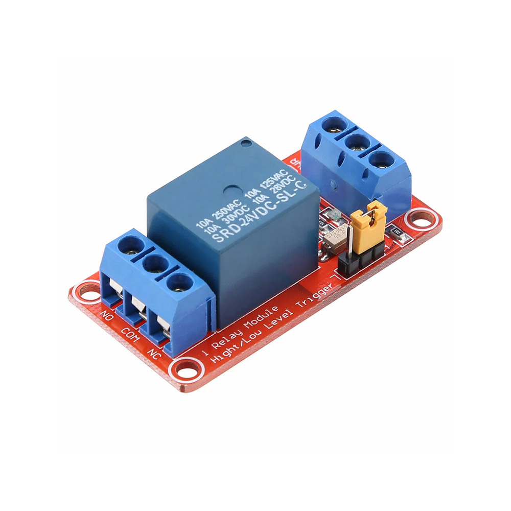 Module relais
Nécessaire lorsque la carte n'a pas de relais. Trois fils vont vers l'ESP32 : commande, alimentation et masse (GND). La sortie du relais va vers la motorisation
Module relais
Nécessaire lorsque la carte n'a pas de relais. Trois fils vont vers l'ESP32 : commande, alimentation et masse (GND). La sortie du relais va vers la motorisation
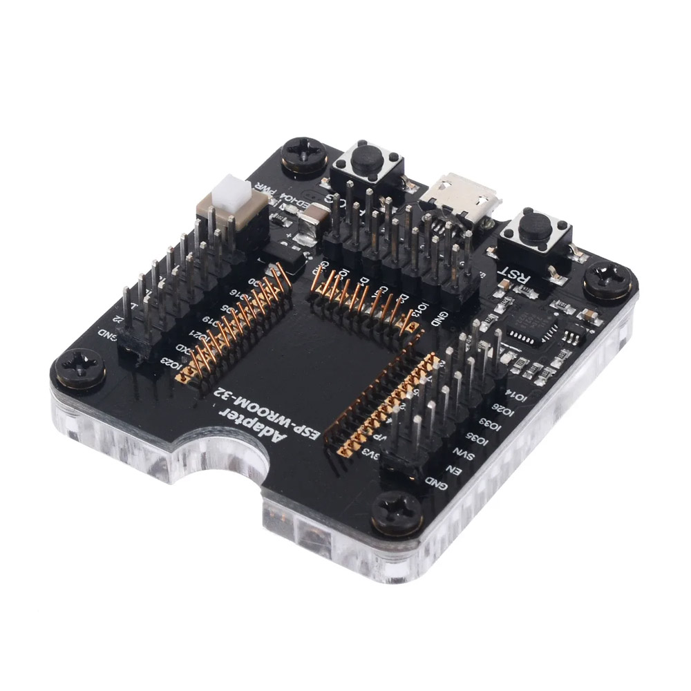 Programmateur avec support
On y insère un module ESP32 ou ESP32-S3 nu pour pouvoir téléverser le programme
Programmateur avec support
On y insère un module ESP32 ou ESP32-S3 nu pour pouvoir téléverser le programme
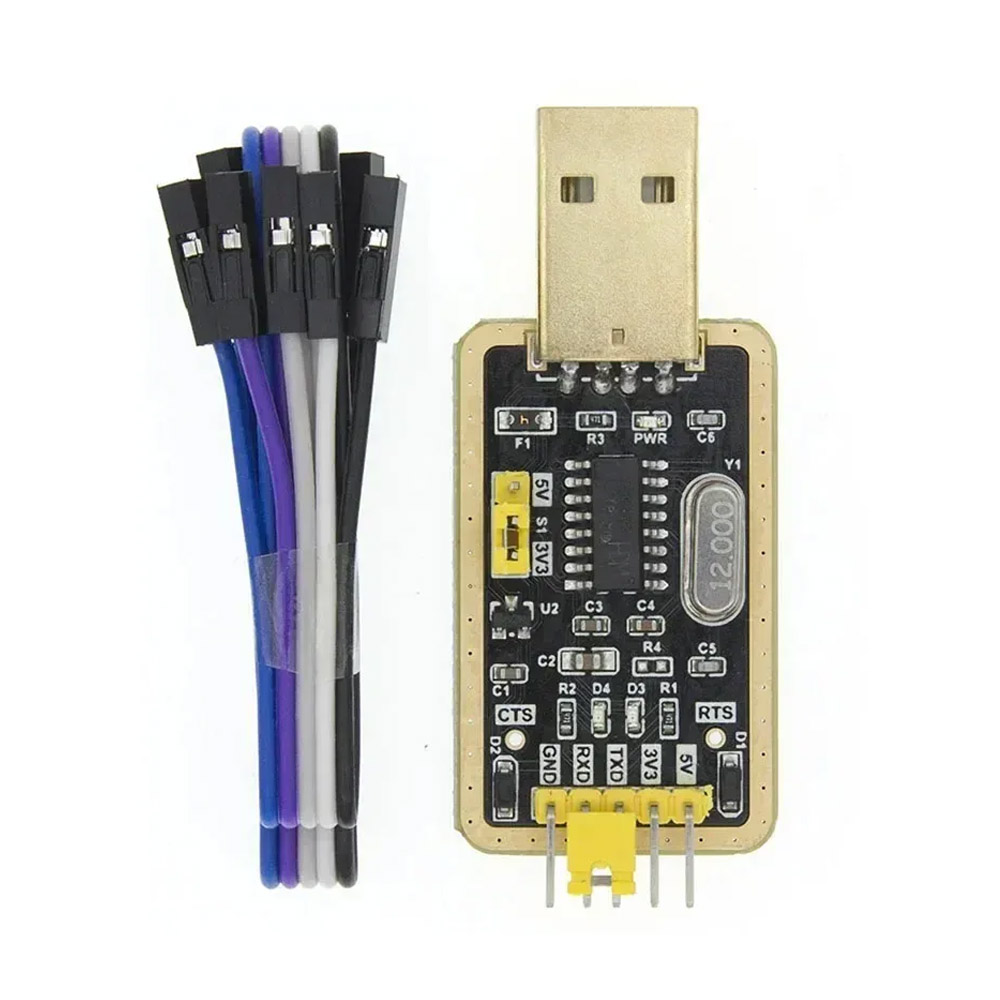 Adaptateur USB-UART
Sert à téléverser le programme sur les cartes relais et sur Shelly — il se raccorde à quelques broches
Adaptateur USB-UART
Sert à téléverser le programme sur les cartes relais et sur Shelly — il se raccorde à quelques broches
2. Carte
Vous ne savez pas quelle puce vous avez ? Reliez la carte à votre ordinateur par un câble USB (un module nu passe par un programmateur) et appuyez sur le bouton — le navigateur détecte la puce et la sélectionne dans la liste ci-dessus. Fonctionne sur ordinateur avec Chrome ou Edge.
3. Serrure et relais
Les masses (GND) du contrôleur et du module relais doivent être reliées — sans masse commune le relais ne fonctionnera pas.
4. Bouton de sortie et fermeture automatique
Sur batterie, le bouton de sortie réveille aussitôt le contrôleur sur un ESP32-S3 (GPIO 0–21) ou ESP32-C3 (GPIO 0–5) ; un ESP32 classique réagit au réveil suivant, dans l’intervalle de sommeil. Le fin de course est lu à chaque réveil. Sur batterie, ajoutez une résistance de 10 kΩ de la broche du bouton vers 3,3 V.
5. LED (facultatif)
Jusqu’à trois voyants : l’état (appairage et impulsion), « ouvert » et, pour une serrure bistable, « fermé ». Sur batterie les LED ne clignotent qu’avec l’impulsion ; la position et le déplacement s’affichent sur secteur (sommeil 0). Inutiles — laissez -1.
6. Bouton d’appairage et diagnostic
7. Alimentation et économie de batterie
8. Horloge externe (facultatif)
Un petit module d'horloge (DS3231, DS1307 ou PCF8563) avec sa propre pile bouton garde l'heure exacte pendant des années. Sans lui, l'horloge interne du contrôleur dérive nettement, d'environ 5 % par heure. Les passes d'invité sur le contrôleur n'expirent à l'heure qu'avec une horloge exacte. Le module est facultatif, vous pouvez sauter cette section.
Compiler et téléverser le programme
Le serveur compile le programme (le micrologiciel) exactement pour vos réglages. Vous pouvez télécharger le fichier ou le téléverser dans le contrôleur directement depuis le navigateur.
Si vous voulez le regarder, le retoucher à la main, télécharger .ino ou partager un lien, appuyez sur "Ouvrir dans l'éditeur". C'est le même code source que le serveur a compilé en .bin.
Ensuite : appairer le contrôleur dans l'application
Après le téléversement, le contrôleur attend un propriétaire pendant 90 secondes en mode appairage. Ouvrez l'application Entrixy dans le rôle propriétaire → Ajouter un objet → BLE — le contrôleur apparaît dans la liste, sélectionnez-le. S'il n'apparaît pas, appuyez sur le bouton d'appairage de la carte : la LED se met à clignoter et la liste se rafraîchit. L'application échange les clés et le contrôleur devient le vôtre. Les détails figurent dans le guide, section "Appairage".
Raccorder le relais à la motorisation
Vous utilisez deux contacts du relais : NO (normalement ouvert) et COM (commun). Ces deux fils vont aux bornes "bouton Ouvrir" de la carte de commande de votre motorisation.
| Motorisation | Où raccorder NO/COM |
|---|---|
| BFT (Phobos, Deimos, Ares) | Bornes START ou OPEN (généralement numérotées 21–22 sur le schéma) |
| CAME (BX, ATI, BK) | Bornes 2–7 (ouvrir), ou PED pour un portillon piéton |
| NICE (Robus, Run, Spin) | Bornes 1–3 (pas à pas) |
| FAAC (740, 844, 391) | Bornes OPEN A (ouverture totale) |
| DoorHan (Sliding, Arm) | Bornes CMD + GND |
| Barrière levante | La borne à bouton-poussoir Ouvrir — en parallèle de ses contacts |
| Interphone (Cyfral, Vizit, Eltis) | Le relais en parallèle du bouton d'ouverture du combiné, ou directement sur les bornes de la serrure magnétique |
Vérifiez les libellés exacts dans le manuel de votre carte de commande. Si la carte est déjà câblée et en service, repérez les deux fils venant de la borne à bouton Ouvrir et raccordez le NO/COM du relais en parallèle.
Téléversement avec esptool (si la voie du navigateur a échoué)
- Téléchargez
.binci-dessus. - Installez esptool :
pip install esptool - Connectez l'ESP en USB.
- Flashez-le :
esptool.py --chip auto --port /dev/ttyUSB0 write_flash 0x0 entrixy-ble.bin - Sous Windows, le port est en général
COM3ouCOM4.
Accéder à l'UART des relais Wi-Fi du commerce
Les appareils tout prêts (Shelly Plus 1, Plus 1PM) n'ont pas d'USB externe. Il faut ouvrir le boîtier et se raccorder aux broches UART de l'ESP32 avec un adaptateur USB-série — CP2102, CH340 ou FTDI, peu importe.
Câblage général
| Adaptateur USB-série | ESP32 sur la carte |
|---|---|
| GND | GND |
| 3.3V | 3V3 (uniquement si vous comptez l'alimenter par l'adaptateur ; sinon, laissez l'appareil sur sa propre alimentation) |
| TX | RX |
| RX | TX |
| — | EN (RESET) — brièvement au GND pour redémarrer dans le bootloader |
| — | GPIO0 — au GND au moment de la mise sous tension, pour entrer dans le bootloader |
Brochage par modèle
| Appareil | Où se trouve l'UART | Entrer dans le bootloader |
|---|---|---|
| Shelly Plus 1 / Plus 1PM | À l'intérieur du boîtier, à côté du module ESP32. Les pastilles sont marquées 3V3 GND TX RX GPIO0. Retirez le capot avant (deux ou trois clips) ; la carte se trouve au-dessus. | Reliez GPIO0 au GND et tirez brièvement EN au GND |
- templates.blakadder.com — une base ouverte de gabarits Tasmota avec les GPIO de chaque modèle. Correspondance avec nos réglages : Relay1 → la broche du relais, Button1 → la broche du bouton, Led1 → la LED d'état.
- devices.esphome.io — le registre ESPHome.
- Si le modèle reste introuvable, prenez un multimètre : sonnez la bobine du relais jusqu'à un GPIO de l'ESP32. C'est votre PIN_RELAY.
Le BLE ne fonctionne que sur l'ESP32. Pour un ESP8266 (Wemos D1, NodeMCU) ou un relais Wi-Fi du commerce, utilisez le configurateur internet — là, la liaison passe par internet.
Si vous préférez ne pas téléverser le programme vous-même
Trois options pour l'éviter :
- Le fabriquer soi-même — prenez une carte ESP32 DevKit (environ 5 $) et n'importe quel module relais 3,3 V (environ 2 $). Une boîte de dérivation fait office de boîtier. Le raccordement à la motorisation est le même que pour un relais industriel. C'est la voie recommandée dans la plupart des cas DIY.
- Un appareil connecté — reflashez un relais Wi-Fi du commerce à contact sec (Shelly Plus 1) avec notre programme dans le configurateur internet, ou laissez-lui son propre micrologiciel et ouvrez-le via un webhook. Le Wi-Fi et le secteur sont nécessaires près de la motorisation.
- Micrologiciel tout prêt d'origine — Tasmota ou ESPHome. Dans l'application, vous créez un objet Webhook avec l'adresse de l'appareil. Cela vous convient si vous préférez ne pas installer notre programme sur l'appareil.