BLE opening controller
Pick a ready-made module or build a controller from a couple of parts, set a few parameters, and upload the finished program into it straight from your browser.
What the firmware does
A phone — the owner's, or a guest's with a valid key — sends the Open command directly over Bluetooth when you are near the controller. The controller closes a pair of the drive's contacts for a short time (one second by default), just like an ordinary button, and opens them again; it does not switch power. For bistable drives and locks you can enable a mode with separate open and close and position tracking in the settings below. Opening happens on a tap in the app; automatic opening as you approach is available too.
What is inside
The link between phone and controller is properly encrypted — it cannot be forged or intercepted. There is nothing to configure, the protection is already built in. Between openings the controller sleeps and uses almost no power.
1. Pick your board
First decide what to build on: take a ready-made modulewhere the controller and the relay are already soldered together, or build it from parts (a separate ESP32 board plus a relay module). Tap your board and we will show how to wire it, while the right settings drop into the form below. At the very end you upload the finished program — also called firmware — into the controller.
Controller boards
ESP32 with a relay on one board
Ready boards with the ESP32 and the relay already soldered together — no separate module needed.
Off-the-shelf Wi-Fi relays (replace the program)
If you want a neat factory case and a certified relay, take an off-the-shelf device and load our program into it instead of its own. Inside it is still an ordinary relay: a pair of contacts that closes for a moment and presses the open button. Such a device does not need its own Wi-Fi — Entrixy talks to the phone directly.
What else you will need
These pictures are not clickable — they just show what the components look like.
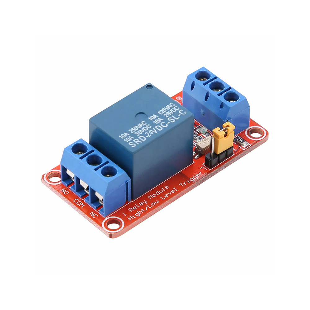 Relay module
Needed when the board has no relay. Three wires go to the ESP32: control, power and ground (GND). The relay output goes to the drive
Relay module
Needed when the board has no relay. Three wires go to the ESP32: control, power and ground (GND). The relay output goes to the drive
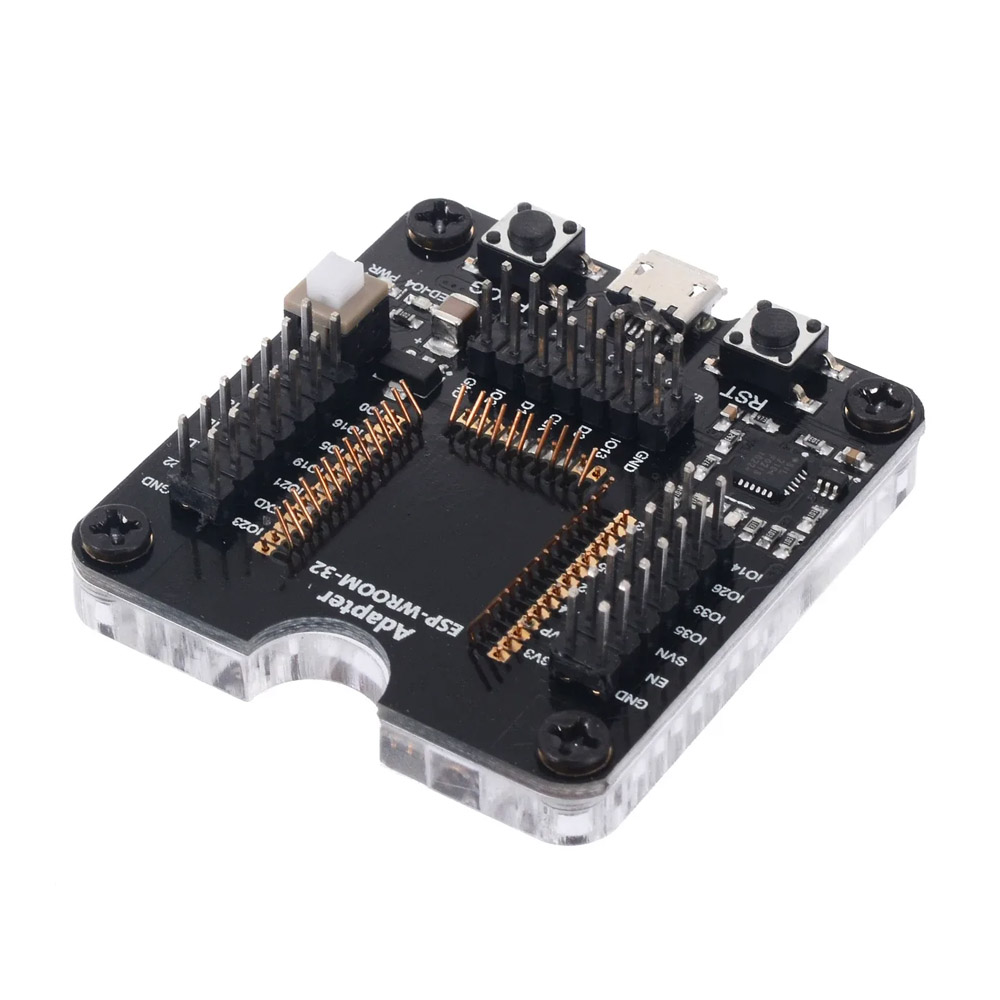 Programmer with a socket
A bare ESP32 or ESP32-S3 module drops into this socket so the program can be uploaded
Programmer with a socket
A bare ESP32 or ESP32-S3 module drops into this socket so the program can be uploaded
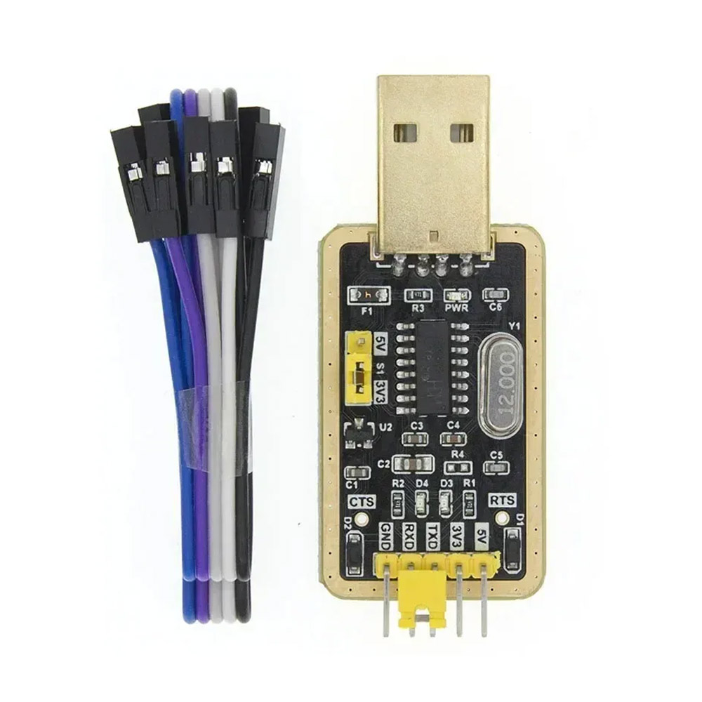 USB-to-UART adapter
Used to upload the program to relay boards and to Shelly — it connects to a few pins
USB-to-UART adapter
Used to upload the program to relay boards and to Shelly — it connects to a few pins
2. Board
Not sure which chip you have? Connect the board to your computer with a USB cable (a bare module goes through a programmer) and press the button — the browser detects the chip and selects it in the list above. Works on a desktop in Chrome or Edge.
3. Lock and relays
The grounds (GND) of the controller and the relay module must be wired together — without a common ground the relay will not work.
4. Exit button and auto-close
On battery the exit button wakes the controller at once on an ESP32-S3 (GPIO 0–21) or ESP32-C3 (GPIO 0–5); a classic ESP32 reacts at the next wake, within the sleep interval. The limit switch is read at every wake. On battery add a 10 kΩ resistor from the button pin to 3.3 V.
5. LEDs (optional)
Up to three indicators: the status (pairing and the pulse), "open" and, for a bistable lock, "closed". On battery the LEDs only flash with the pulse; the position and the way are shown on mains power (sleep 0). Leave them at -1 if you do not need them.
6. Pairing button and diagnostics
7. Power and battery saving
8. External clock (optional)
A small clock module (DS3231, DS1307 or PCF8563) with its own coin cell keeps accurate time for years. Without one the controller's internal clock drifts noticeably, by roughly 5% an hour. Guest passes on the controller expire on time only with an accurate clock. The module is optional, and you can skip this section.
Building and uploading the program
The server builds the program (the firmware) for exactly your settings. You can download the file or upload it into the controller straight from the browser.
If you want to look at it, tweak it by hand, download .ino or share a link, press "Open in the editor". It is the same source the server compiled into .bin.
Next: pair the controller in the app
After the upload the controller waits 90 seconds for an owner in pairing mode. Open the Entrixy app in the owner role → Add object → BLE — the controller appears in the list, select it. If it does not, press the pairing button on the board, the LED starts blinking and the list refreshes. The app exchanges keys and the controller becomes yours. Details are in the guide, section "Pairing".
Connecting the relay to the drive
You use two contacts on the relay: NO (normally open) and COM (common). These two wires go to the "Open button" terminals on your drive's control board.
| Drive | Where to connect NO/COM |
|---|---|
| BFT (Phobos, Deimos, Ares) | Terminals START or OPEN (usually numbered 21–22 in the diagram) |
| CAME (BX, ATI, BK) | Terminals 2–7 (open), or PED for a pedestrian gate |
| NICE (Robus, Run, Spin) | Terminals 1–3 (step-by-step) |
| FAAC (740, 844, 391) | Terminals OPEN A (open fully) |
| DoorHan (Sliding, Arm) | Terminals CMD + GND |
| Boom barrier | The Open push-button post — in parallel with its contacts |
| Intercom (Cyfral, Vizit, Eltis) | The relay in parallel with the door release button on the handset, or straight onto the magnetic lock terminals |
Check the exact labels in your control board's manual. If the board is already wired and working, find the two wires running from the Open push-button post and connect the relay's NO/COM in parallel with them.
Uploading with esptool (if the browser route failed)
- Download
.binabove. - Install esptool:
pip install esptool - Connect the ESP over USB.
- Flash it:
esptool.py --chip auto --port /dev/ttyUSB0 write_flash 0x0 entrixy-ble.bin - On Windows the port is usually
COM3orCOM4.
Getting to the UART on off-the-shelf Wi-Fi relays
Ready-made units (Shelly Plus 1, Plus 1PM) have no external USB. You have to open the case and connect to the ESP32's UART pins with a USB-to-serial adapter — CP2102, CH340 or FTDI, any of them.
General wiring
| USB-to-serial adapter | ESP32 on the board |
|---|---|
| GND | GND |
| 3.3V | 3V3 (only if you intend to power it from the adapter; otherwise leave the device on its own supply) |
| TX | RX |
| RX | TX |
| — | EN (RESET) — briefly to GND to reboot into the bootloader |
| — | GPIO0 — to GND while powering up, to enter the bootloader |
Pinout by model
| Device | Where the UART is | Entering the bootloader |
|---|---|---|
| Shelly Plus 1 / Plus 1PM | Inside the case next to the ESP32 module. The pads are labelled 3V3 GND TX RX GPIO0. Take off the front cover (two or three clips); the board sits on top. | Tie GPIO0 to GND and briefly pull EN to GND |
- templates.blakadder.com — an open database of Tasmota templates with the GPIOs for each model. It maps onto our settings as: Relay1 → the relay pin, Button1 → the button pin, Led1 → the status LED.
- devices.esphome.io — the ESPHome registry.
- If the model is nowhere to be found, reach for a multimeter: ring out the relay coil back to an ESP32 GPIO. That is your PIN_RELAY.
BLE works on the ESP32 only. For an ESP8266 (Wemos D1, NodeMCU) or an off-the-shelf Wi-Fi relay use the Internet configurator — there the link runs over the internet.
If you would rather not upload the program yourself
Three options that avoid it:
- Build it yourself — take an ESP32 DevKit board (about $5) and any 3.3 V relay module (about $2). A junction box makes the enclosure. It wires to the drive just like an industrial relay. This is the recommended route for most DIY cases.
- An internet device — reflash an off-the-shelf Wi-Fi relay with a dry contact (Shelly Plus 1) with our program in the Internet configurator, or keep its own firmware and open it through a webhook. Wi-Fi and mains power are needed next to the drive.
- Ready-made firmware out of the box — Tasmota or ESPHome. In the app you create a Webhook object with the device's address. This suits you if you would rather not put our program on the device at all.