Raspberry Pi — opening over the internet
Fill in a few parameters and the server builds a finished Python script for your board. All that is left is to copy it onto the Raspberry Pi and run it as a service: there is nothing to flash.
1. Platform
Choose a platform — the fields that follow depend on it.
2. Ready presets
Tap a preset and its parameters drop into the form below. You can adjust them by hand afterwards.
Off-the-shelf Wi-Fi relays (replace the program)
Build it yourself on an ESP32
ESP8266 controller boards
Off-the-shelf ESP8266 Wi-Fi relays (Sonoff and the like) will not drive a gate: they switch mains voltage and have no dry contacts. You need a plain board plus a separate relay module (see "What else you will need" below) — that is what gives you a free pair of contacts that acts like a button.
Raspberry Pi
On an ordinary Pi the relay hangs off the GPIO — the same relay module as for the ESP (see "What else you will need" below). Or take a relay HAT that sits straight on the Pi's header.
What else you will need
These pictures are not clickable — they just show what the components look like.
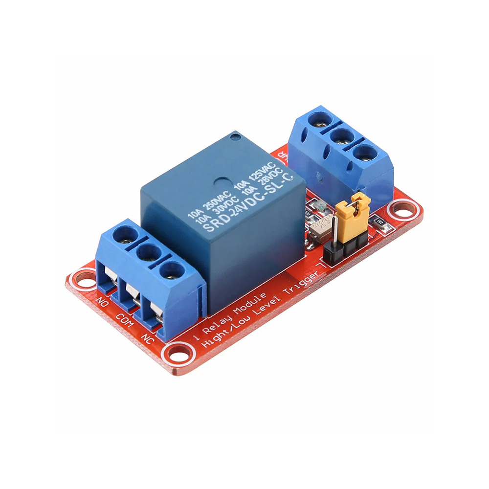 Relay module
The same one for an ESP32, an ESP8266 or a Raspberry Pi — any board without an on-board relay. Three wires to the controller: control, power and ground (GND). The relay output goes to the drive
Relay module
The same one for an ESP32, an ESP8266 or a Raspberry Pi — any board without an on-board relay. Three wires to the controller: control, power and ground (GND). The relay output goes to the drive
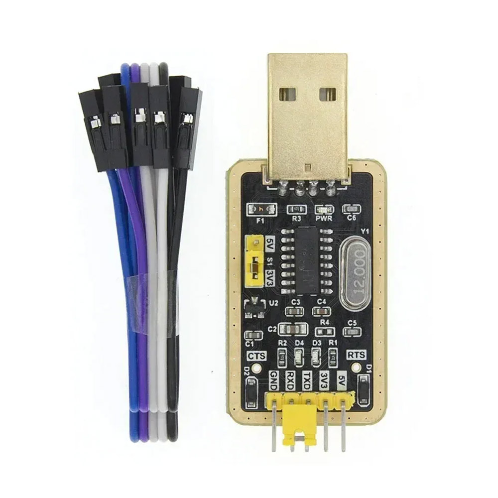 USB-to-UART adapter
Needed when there is no USB of your own: ready Shelly units and bare ESP32/ESP8266 modules. Boards with USB (DevKit, Wemos) do not need it
USB-to-UART adapter
Needed when there is no USB of your own: ready Shelly units and bare ESP32/ESP8266 modules. Boards with USB (DevKit, Wemos) do not need it
3. WiFi
The network name and password are written into the device's program. If you change your Wi-Fi later, you will have to rebuild and upload the program with the new details.
3. Network
A Raspberry Pi connects to the network through the operating system — Wi-Fi or Ethernet is configured with the standard raspi-config, NetworkManager or /etc/wpa_supplicant/wpa_supplicant.conf. The script itself needs no Wi-Fi credentials.
Setting one up for the first time? On a Pi Zero W it is easiest to put the SSID and password on the SD card's boot partition in the file wpa_supplicant.conf. On a Pi 4 or 5 it is simpler with raspi-config nonint do_wifi_country RU and raspi-config nonint do_wifi_ssid_passphrase MyHomeWiFi secret.
4. Device credentials
In the app add an object of type "Device" — once registered, the app shows the device code. Paste it into the field below: the firmware uses it to connect to the server.
5. Lock and relays
6. Exit button and auto-close
The button and the limit switch use the pin's internal pull-up, no resistor needed. On an ESP32, pins 34–39 have no pull-up and cannot be used for them: pick another pin.
The button and the limit switch use the pin's internal pull-up, no resistor needed. On an ESP8266 avoid GPIO16 (no pull-up) and GPIO0, 2 and 15: they decide how the board starts. GPIO4, 5, 12, 13 and 14 are safe.
7. LEDs (optional)
Up to three indicators: the server connection, "open" and, for a bistable lock, "closed". Leave them at -1 if you do not need them.
If you want to read the source, tweak it by hand, download .ino or share a link, press "Open in the editor". It is exactly the code the server compiled into .bin.
Bind to the app
In the app open the Device object → "Bind to the app", copy the code (it starts with ENTX-BIND:), paste it below and press "Write to the controller". After that the controller opens only on a command from your app — the secret travels to it over USB, bypassing the network and the server.
The controller must already be flashed and connected over USB. If the app has reissued the key, repeat the binding with the new code.
Easier: paste the code here before pressing "Upload to the controller" — the key is written right after the firmware, in the same USB session.
Installing on a Raspberry Pi
Once you have downloaded the configured entrixy.py:
- Put the file in
/opt/entrixy/entrixy.pyon the Pi (you can usescp). - Install the dependencies:
sudo apt install python3-websockets python3-rpi.gpio(on a Pi 5 usepython3-rpi-lgpio). - Download the systemd service: entrixy.service, put it in
/etc/systemd/system/. - Enable it at boot:
sudo systemctl enable --now entrixy. - Check it:
sudo journalctl -u entrixy -f→ you should seeauth OK.
The script reconnects by itself when the link drops and comes back after the Pi reboots.
Connecting the relay to the drive
You use two contacts on the device's output: NO (normally open) and COM (common). These two wires go to the "Open button" terminals on your drive's control board.
| Drive | Where to connect NO/COM |
|---|---|
| BFT (Phobos, Deimos, Ares) | Terminals START or OPEN (usually numbered 21–22 in the diagram) |
| CAME (BX, ATI, BK) | Terminals 2–7 (open), or PED for a pedestrian gate |
| NICE (Robus, Run, Spin) | Terminals 1–3 (step-by-step) |
| FAAC (740, 844, 391) | Terminals OPEN A (open fully) |
| DoorHan (Sliding, Arm) | Terminals CMD + GND |
| Boom barrier | The Open push-button post — in parallel with its contacts |
| Intercom (Cyfral, Vizit, Eltis) | The relay in parallel with the door release button on the handset, or straight onto the magnetic lock terminals |
Check the exact labels in your control board's manual. If the board is already wired and working, find the two wires running from the Open push-button post and connect NO/COM in parallel with them.
Getting to the UART on off-the-shelf Wi-Fi relays
The ready Shelly Plus 1 unit has no external USB. You have to open the case and connect to the UART pins with a USB-to-serial adapter — CP2102, CH340 or FTDI, any of them.
General wiring
| USB-to-serial adapter | Device |
|---|---|
| GND | GND |
| 3.3V | 3V3 |
| TX | RX |
| RX | TX |
| — | EN/RESET — briefly to GND to reboot into the bootloader |
| — | GPIO0 — to GND while powering up, to enter the bootloader |
Pinout by model
| Device | Where the UART is | Entering the bootloader |
|---|---|---|
| Shelly Plus 1 / 1PM (ESP32) | The pads inside the case next to the ESP32 module | Tie GPIO0 to GND and briefly pull EN to GND |
Uploading with esptool (if the browser route failed)
- Download
.binabove. - Install esptool:
pip install esptool - Connect the device to USB or to a USB-to-serial adapter.
- Flash it:
esptool.py --chip auto --port /dev/ttyUSB0 write_flash 0x0 entrixy-ws.bin - On Windows the port is usually
COM3orCOM4.